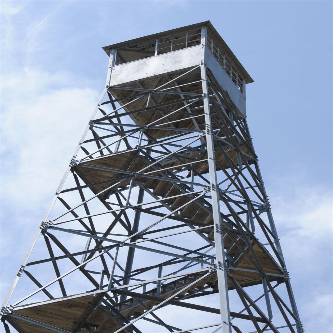
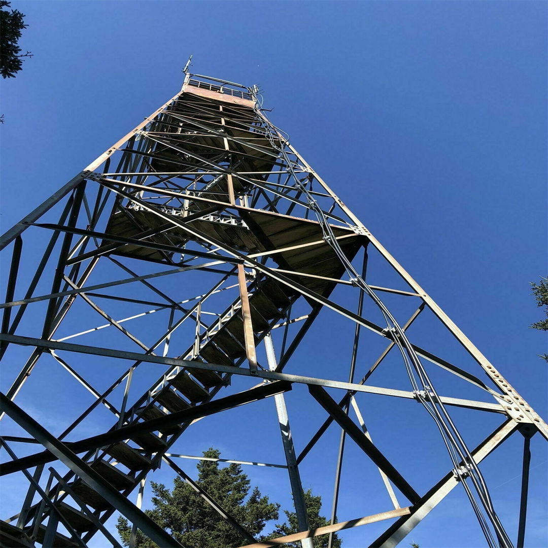
Antenna feeders, power cables, optical fibers and grounding cables are essential signal and power transmission media for every telecom base station. Poor cable layout and messy installation will increase extra wind load, cause cable abrasion, water ingress, signal attenuation and difficult troubleshooting. In severe cases, swinging loose cables may strike antennas or twist tower components under strong wind, creating hidden safety hazards.
A standardized cable management system including ladder racks, cable trays, clamps and cable hangers organizes all cables neatly, minimizes additional wind‑induced stress, protects cable outer jackets and greatly simplifies routine inspection and upgrade work. As a full‑set telecom infrastructure supplier, JIAYAO pre‑designs cable mounting interfaces for all tower products. This guide covers core components, design principles, installation rules and maintenance recommendations for tower cable management.
Cable ladder rack is the primary supporting structure for feeders and power cables along tower shaft, widely used on lattice towers and tri‑tubular towers. It consists of two longitudinal side rails and transverse rungs.
Material: Hot‑dip galvanized steel, corrosion‑resistant aluminum alloy for coastal sites.
Features: Open‑style structure for good ventilation, easy access for cable installation and later modification.
Installation: Bolted onto tower main members along vertical direction, continuous from base platform up to top equipment platform.
Application: Large‑diameter coaxial feeders, multi‑core power cables and optical fiber bundles.
Closed or semi‑closed trough‑type cable supporting structure.
Types: Solid bottom tray and perforated ventilation tray. Perforated trays are preferred for outdoor towers for water drainage.
Advantages: Provide better mechanical protection for optical fibers and thin‑diameter signal cables against sun, rain and flying debris.
Limitation: Higher wind‑loading compared with open ladder racks, avoid full‑width closed trays on high‑wind zone towers.
Application: Rooftop towers, monopole internal cable routing and small cell pole projects.
Cable clamps are used to fix individual cables onto ladders or tower body, preventing cable swing under wind vibration.
Two common types: single‑cable clamp and multi‑cable bundle clamp. Rubber lining inside prevents crushing and abrasion of cable outer sheath.
Spacing rule: Vertical installation: clamps every 1.5‑2 m; horizontal crossarm section: clamps every 1‑1.5 m.
Special note: Do not over‑tighten clamps to avoid deforming cable jackets.
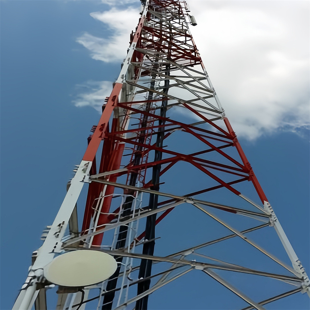
Cable glands & waterproof entry plates: At tower base cabinet position, prevent rainwater from flowing along cables into equipment cabinets.
Cable bend‑control fixtures: Maintain minimum bending radius for feeders and optical fibers to avoid signal loss caused by excessive bending.
Grounding kits: Feeder cable grounding clamps installed at top, middle and bottom positions of vertical runs for lightning surge diversion.
Strain relief hangers: Bear the self‑weight of long vertical cables, prevent tensile force transferring onto antenna connector ports.
For monopole towers, most cables run inside the pole shaft. Special internal mounting brackets are pre‑welded inside the tube to fix ladders and clamps, avoiding cables swinging freely within the pole cavity. Access openings at the base facilitate cable pulling work.
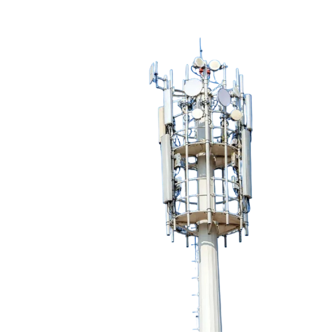
Loose, disorderly bundled cables significantly increase wind‑facing area, which may raise total tower wind load by 10%‑25%.
Keep cables close to tower main structure instead of hanging out in free air.
Avoid large‑diameter closed trays for high‑wind and typhoon‑prone locations, select open ladder racks.
Group cables neatly, do not allow scattered separate cables fluttering in wind.
Each cable type has strict minimum bending radius limits.
Large coaxial feeder: bending radius ≥15 times cable outer diameter.
Optical fiber cable: bending radius ≥20 times cable outer diameter.
All bends on tower must satisfy these values to prevent internal conductor damage and increased signal attenuation.
Power cables, RF feeders and optical fibers should be placed in separate zones on the ladder rack to reduce electromagnetic interference.
Maintain clear segregation between high‑voltage power lines and signal cables.
Reserve spare space (30% extra capacity) on ladder racks for future network upgrade and new‑cable addition.
All horizontal cable runs maintain slight downward slope towards equipment side, preventing rainwater flowing along cable sheaths into antenna connectors or cabinets.
Use waterproof glands at cabinet entry points; avoid forming water‑trapping loops on cables.
All metal components of cable management system (ladders, trays, clamps) must be bonded to tower main body to achieve equipotential grounding, preventing potential difference during lightning strikes.
1. Lattice / Tri‑tubular tower
2. Mount vertical cable ladder rack along one tower leg from ground platform to top platform. Install cross‑arm short ladder sections for antennas and microwave equipment. Fit strain relief hangers for heavy feeders at top platform. Route grounding cables together with signal cables but maintain physical separation.
3. Monopole tower
4. Run most cables inside the pole shaft, fixed by internal brackets. Only short segments go outside for antenna connection. Use the base access door for cable pulling work. Avoid excessive cables piled inside the pole cavity.
5. Rooftop tower
6. Use perforated cable trays. Route cables along rooftop building cable channels wherever possible. Avoid random cable laying across roof waterproof layers. Keep sufficient bending radius when turning from rooftop up to tower antennas.
7. Guyed wire tower
8. Mount ladder rack on main mast. Keep all cables clear from guy wires; prevent cables from rubbing against guy strands during wind vibration.
1. Insufficient clamps leading to long‑length free‑hanging cables that swing violently in wind, causing jacket wear and connector loosening.
2. Sharp bending of feeders or optical fibers below minimum radius, resulting in permanent signal performance degradation.
3. Over‑tightened clamps crushing cable outer rubber jackets, causing water penetration and premature cable failure.
4. No strain relief hangers: full vertical weight of long feeders pulls directly on antenna connectors, leading to intermittent connection faults.
5. Mixed laying of power and RF signal cables without separation, bringing electromagnetic interference risk.
6. Ignoring equipotential bonding for ladder racks, creating dangerous voltage potential difference under lightning conditions.
1. Quarterly visual inspection: Check clamp tightness, confirm no loose or dangling cables. Look for cracked, worn or aged cable jackets.
2. Check grounding connections: Ensure ladder and tray bonding points are intact, no corrosion at contact surfaces.
3. After strong wind or typhoon: Inspect for cable displacement, abrasion caused by friction against tower members.
4. During equipment upgrade: Add new clamps for newly‑installed cables; do not simply lay new cables over old ones. Remove redundant abandoned cables to reduce extra wind load.
5. Coastal salt‑spray sites: Inspect galvanized accessories for corrosion every year; touch‑up damaged zinc coating with zinc‑rich paint.
JIAYAO provides complete matching cable management accessories for all tower series:
Pre‑reserved bolt mounting points for ladder racks and clamps during tower manufacturing, no on‑site welding required.
Supply hot‑dip galvanized steel or aluminum‑alloy ladders, trays, rubber‑lined cable clamps, strain relief hangers and grounding accessories.
Provide layout drawing showing ladder routing, clamp spacing and cable separation suggestions.
Custom solutions for monopole internal cabling, coastal anti‑corrosion upgrade and high‑wind‑area special requirements.
Cable management is often underestimated in tower construction, yet it directly impacts signal quality, wind‑load safety and long‑term maintenance efficiency. Scientific layout, correct component selection and standardized installation can effectively reduce cable‑related failures and reserve upgrade space for future 5G/6G network evolution.
If you need cable management configuration advice for your telecom tower project, please contact JIAYAO for technical support and quotation.